
21.02.2024
Lifehacks and features of NanoCAD

NanoCAD Lifehacks
NanoCAD is a modeling platform from Russian developers. NanoCAD allows you to create plans, projects of any complexity and size. For efficient operation, the application combines BIM and CAD technologies, supporting several formats. Many modules have also been released that allow you to expand the functionality of the program. Below we will tell you about the features of working with NanoCAD and give useful recommendations.
Features of NanoCAD
The platform is often used by architects, engineers and designers because it has a number of features that distinguish it from its competitors:
- The basis for working with BIM technologies. The program already contains basic tools and capabilities for 3D modeling. Many additional modules are installed on this basis to organize the joint work of several project teams.
- High performance. All streams and capacities of the video card are used to process information. Thanks to the latest achievements in the field of algorithmization, developers have managed to achieve high speed.
- Open API. The ability to create modules and tools yourself makes NanoCAD's functionality almost limitless. The platform integrates with electronic document management, imports and exports various data and configures tools that are relevant specifically to your industry.
Tips for working with NanoCAD
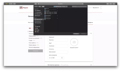
Now that we have figured out what NanoCAD is, what this system is used for and what advantages it has, let's move on to life hacks for working with the BIM platform. The first function you will see in the interface of this module is "Project Manager". It allows you to access and work with various files:
- specifications;
- drawings;
- calculations based on 3D models and others.
Floors
The main task of BIM is to create and arrange 3D models of buildings. Most often they are multi-story. Therefore, for competent work with the platform, it is important to understand the principle by which floors work. They are created in the "Water Supply" tab, click on the corresponding option. After that, they will appear in the project managers and will be presented as a separate file in .dwg format. An important parameter of this document is the height mark at which the floor is located.
It is important to understand that when working with each individual floor, you enter coordinates relative to its height. But it is designated in the program as zero. If you want to see the state of the floor on the plan relative to the entire building, go to the "Building Model". The modeling of floors is simple: you arrange floors separately, and then, using the program, assemble them together, obtaining a full-fledged model of a multi-story building.
It is also important to understand the nuances of creating underground floors. They are checked for collisions. The underground parts of the building themselves have a negative mark, for example, -3,000 meters. Also underground are water pipes, for example, at a depth of -1,800 meters. Because of this, when modeling the pipe, the difference is taken into account. Therefore, in the value of its height, +1,200 is indicated. This is the height relative to the zero point of the underground floor, and not the entire building. Therefore, the pipeline will still be located underground at a mark of -1,800 meters.
Constructions
Another important element of any model is the structure. Some structures, such as trusses or reinforcement frames, are based on multi-component structures. It is important to consider each element to calculate the load-bearing capacity and stability of a building. The approach simplifies the creation of similar parts of models and the calculation of the required amount of building materials.
The easiest way to assemble structures is to use ready-made models from the program database, for example, a staircase with railings. But the difficulty arises when the basic models have to be edited or modified. For example, remove the railings from the staircase plan. After you do this, save the new model to the database. Then you will not have to edit each staircase in the building: use the model you made several times.
Thanks to this feature, each object of the program file base is flexibly edited, adapting to the needs of a particular project. Thus, the speed of creating new designs increases several times.
Elements in ceilings and walls
Some parts of the building are located inside the floors and walls. Let's take doorways as an example. They will need to be copied several times. To do this, right-click on the model and select the appropriate option. After that, select the base point on the object. There is a convenient function "Specify surface for connection". It allows you to integrate the opening into any suitable surface. After that, it moves in any direction and changes in size without any difficulties.
The article was useful to you?
0
146
1